

Power Fiber Combiner
1.0 Description
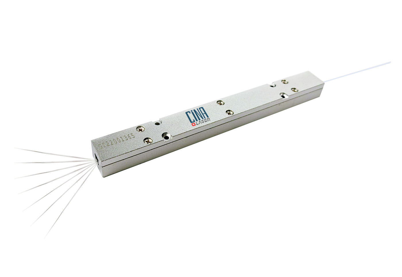
Power Fiber Combiner(PFC) is one of the key components to break through the power scaling limitation of a single fiber laser by combing several high power fibers into a single fiber to realize the higher output power.
| Item | Specifications | Unit | Notes | ||||||||||||||
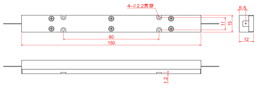
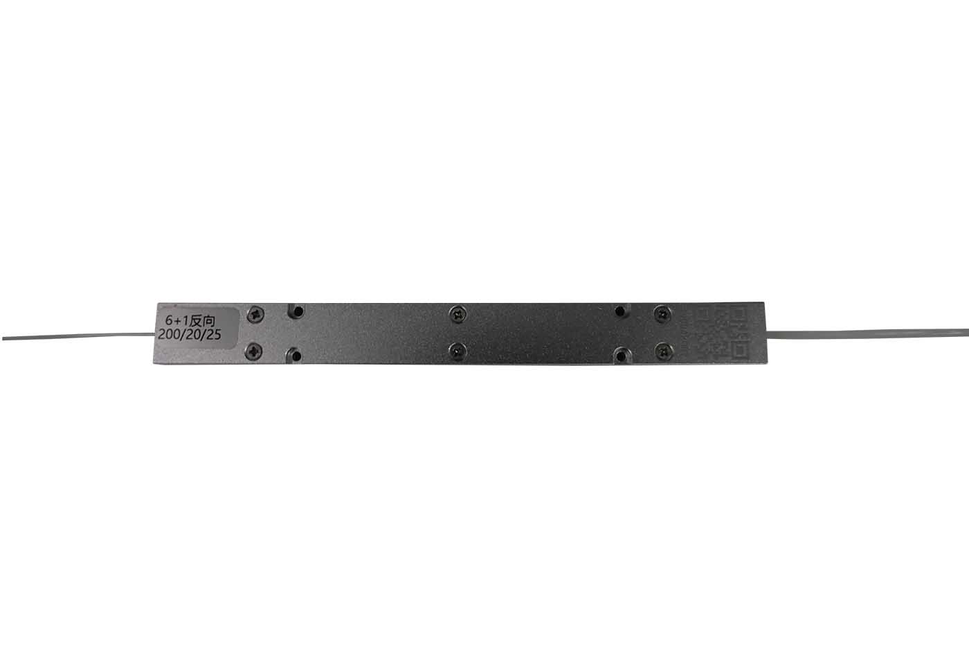
| 4.01 | Module’s Dimensions-B | 150*15*12 | mm | Bottom conduction cooling | |||||||||||||
 |
|||||||||||||||||
| Item | Specifications | Min. | Typ. | Max. | Unit | Notes | |||||||||||
| 2.01 | Signal wavelength | 1000 | 1060 | 1100 | nm | ||||||||||||
| 2.02 | Polarization | Random | PM Customizable | ||||||||||||||
| 2.03 | Operation regime | CW | |||||||||||||||
| 2.04 | Fiber length | 2.0 | m | Default | |||||||||||||
| 2.05 | M2 | ≤5 | Customizable | ||||||||||||||
| 5.5 | For 50μm Core Diameter | ||||||||||||||||
| 10 | For 100μm Core Diameter | ||||||||||||||||
| 2.06 | Operating temperature range | 0 | +70 | °C | |||||||||||||
| 2.07 | Storage temperature | -40 | +85 | °C | |||||||||||||
3.0 Output fiber and termination options
| Item | Configuration | Input Fiber Type | Output Fiber Type | Power Handling | Efficiency | ||||||||||||
| 3.01 | 3×1 | X/250 DCF, NA:0.06/0.46 | 100/120/360, NA:0.22/0.46 | 5kW/leg | >96% | ||||||||||||
| 3.02 | 7×1 | X/250 DCF, NA:0.06/0.46 | 100/120/360, NA:0.22/0.46 | 3kW/leg | >96% | ||||||||||||
* X=25 etc.
* Better performance and other configuration can all be customized.
| PFC-①-②-③-④-⑤/⑤-⑥ | |||||||||||||||||
| ①:Port combination | ②:Input fiber type | ③:Output fiber type | |||||||||||||||
|
3 – 3×1 7 – 7×1 |
D06 – 20/250 DCF, 0.06NA D07 – 25/250 DCF, 0.06NA ect. |
T01 – 100/120/360, NA:0.22/0.46 ect. |
|||||||||||||||
| ④:Handling power per port | ⑤/⑤:Input/Output fiber length | ⑥:Package type | |||||||||||||||
|
3KW – 3.0Kw 5KW – 5.0Kw ect. |
1.5 – 1.5m Default 2.0 – 2.0m 3.0 – 3.0m ect. |
A1 = Aluminum package 150*15*12mm | |||||||||||||||
| For example:PFC-3-D07-T01-3KW-1.5/1.5-A1 | |||||||||||||||||

 CINA Laser
 CINA Laser

 1A, Building1, 7 Xiyuan Rd, Hangzhou 310030, China
 sales@cinalaser.com
 +86(0571)86992687

